Dad, it is almost as super as a train
Overview
This is the second version of my robot car. The first version had some problems, most importantly the power distribution was ill-designed (more precisely, it was not designed at all).

What’s new
With this second version I fixed most of the problems of the first version (and probably introduced some brand new ones), and made it more versatile adding new hardware elements:
-
The car got brand new chassis, home made from MDF wood. It is bigger, nicer and more kid friendly being also a LEGO platform.
-
The power distribution is redesigned. The robot got a nice 3S LIPO battery, and an [LM2596](http://www.ti.com/product/LM2596 based switching power regulator . The power rail is regulated to 9V, which is more than what the motors require (6V), but they endure it and run faster.
-
The microcontroller is updated to an Arduino Mega from the Arduino Nano. More pins, more timers, more possibilities…
-
A GY80 based Inertial Measurement Unit (IMU) is added. It’s a compact module that includes a gyroscope, accelerometer, digital compass, and a barometric pressure / temperature sensor. The sensors are not used as now, but I plan to utilize some of them in the future (e.g. to let the robot going more straight).
-
Nice headlights are made from 4 power leds. I also had to develop a small driver circuit as the LEDS would draw a way too much power from the Arduino. The LEDS are installed in a nice 3D printed mount.
-
Wiring is slightly improved. I used heat shrinks and made custom length jumper wires. It already looks a way less messy and safer than the previous version, even if there is room for improvement yet.
All together, it looks and works much better than the previous version. The chassis looks kind of “crafted”, especially compared to the old acrylic one, and the 9V power rail makes the robot more reliable and faster. The extra sensors makes it more like a “real” robot, and provides stable ground for future experiments. And last, but not least, the new headlights are hugely popular with the kids.

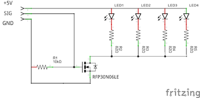
LED driver
I built the LED driver on half of 2x8 cm perfboard using the following parts:
- 1 x RFP30N06LE N-Channel MOSFET
- 4 x 82R resistor (for 20mA LEDS, calculate here otherwise)
- 1 x 10K resistor (pull-down)
- some pin headers
And the schematics:
List of parts and cost
The chassis is inexpensive, made from wood, I already posted about it. The robot also contains many 3D printed parts which I consider as zero cost. These parts are the following:
- 4 x Motor mounts
- 2 x LED mounts
- 1 x HC-SR04 mount
- 1 x LIPO battery mount (It is different than on the picture. I currently use an advanced design that enables me to change the battery without removing the cover of the robot)
(The list excludes ubiquitous items like jumper wires, heat sinks, etc. It also excludes general equipment like LIPO battery charger)
| Part | Price |
|---|---|
| Arduino Mega | ~6$ |
| L298N x 2 | < 2$ x 2 |
| Motors + wheels | ~5$ |
| PS2 controller + receiver | ~ 10$ |
| Piezo buzzer (salvage it from an old toy) | < 1$ |
| 10 mm LEDs | ~2$ (10 pieces) |
| < 2$ | |
| HC-SR04 | < 1$ |
| GY80 IMU | ~14$ |
| 2200ma 3S LIPO battery | ~12$ |
| Chassis | ~20$ |
| < 76$ |
Problems
The power distribution works perfectly 99% of the cases now, but the microcontroller still resets when the motors are reversed at maximum speed. The problem is with the voltage regulator as it limits the current to 2A (despite that by specification it should be able to deliver 3A temporarily). The robot draws ~1.6A at 9V at full speed, so there is no much room for the inrush current when the motors start. It is probably an easy fix by adding some decoupling capacitors, or replacing the voltage regulator with e.g. an XL4015 (or adding a second voltage regulator for the electronics creating this way another power rail). I believe it is also possible to solve this issue from software. I eliminated the problem temporarily by regulating to 6V instead of 9V.
Future work (this robot)
The hardware works as expected, now I want to concentrate on the software (including a fix for the resetting problem) as it is the weakest point currently. First of all, the individual components (wheels, lights, sensors, etc…) should register themselves instead of being hard wired. I also want some filtering on the sensor inputs (I mean e.g. Kalman filters). It would be also nice to use a PID controller and exploiting the new sensors to make the robot going more straight (the cheap wheels and the hand made chassis renders the trajectory of the robot slightly imprecise). I also would like to make some experiments with OOSMOS to find out whether it is good enough to replace the simple green thread library used currently.
Future work (next robot)
-
Power distribution: I want a power distribution board. Mostly to avoid ad-hoc wiring harnesses, but some fuse would be useful as well. I can also imagine the voltage regulator(s) integrated. It is really strange that there are no general purpose power distribution boards available for robotics. Especially considering how helpful they are. Actually, the multirotor community already realised that.
-
Wiring: I read somewhere that robotics is all about wiring and connectors. I could not agree more. Some of my vague ideas: 3D printed wire channels, IDC header socket connectors, custom arduino shields. I really want to get rid of these unreliable dupont jumper wires.
-
DC motors: Better motors, more torque and also more speed. It is going to be easy regarding how crappy motors I have now. I also want encoders feeding the PID controller.
-
Wheels: Mecanum wheels…
-
Software: Instead of C/C++, I would like to use a dependently typed functional language for developing the software. I believe that robotics is exactly the field where extra type safety pays back. There are not so many dependently typed languages though. I tried Idirs, but, although I really like the language, the generated code is a way too inefficient. The other option is GHC/Haskell. It is not officially dependently typed, but its type system is powerful enough to emulate it, and the upcoming version will officially provides this feature (to the extent I need it). The problem is that Haskell is lazy, what makes it unpractical for embedded applications (in the upcoming version this is optional) and it is garbage collected what renders it unusable on microcontrollers. But, why should it run on a microcontroller anyway?
-
Computer/microcontroller: I have no problem with Arduino, but it is not powerful enough to run my Haskell code. So I need a real computer, like Raspberry Pi, but I also need real time support provided by a microcontroller. I could use a Raspberry with an Arduino in pair, but actually I think Raspberry is just not a good embedded system. Mostly, because it is not an embedded system. Raspberry Zero is closer, but still. Intel Edison seems a much better choice. Powerful enough with integrated microcontroller. Sounds just perfect.