After I finished the delta robot, I felt confident enough to create something from scratch instead of following instructions. I inquired my kids whatever they wanted and they opted for building a train. I really do not understand children’s obsession for trains… Anyway, being a really bad person, I convinced them that cars are cooler (actually I believe that trains are cooler, but tracks make them impractical).
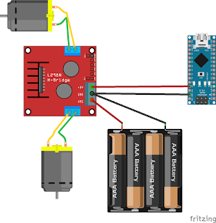
It was a 4 wheels robot car basically built from some cheap Chinese 6V DC motors, two L298N dual motor controllers and an Arduino Nano. The whole stuff was powered by 4 AA batteries. The relevant part of the electronics was quite straightforward: the batteries were directly connected to the L298N; the L298N has regulated 5V output, that was used to power the Arduino. This configuration, however, simple as it is, has many things wrong with it.
1. problem: low voltage
While being built, the robot was always connected to my laptop with a USB cable. When the wireless controller arrived, I worked half a night to integrate it and develop the software, I was extremely excited being that close to an actual test drive. And finally it worked on the bench pad, ready to test! USB cable was removed, the car was switched on… nothing happened. USB cable was plugged in again, car was switched on, worked perfectly. USB cable disconnected again… nothing happened.
It was immediately clear what was happening. The battery did not have enough power to drive the voltage regulator (what is rather amazing that I did not realize this problem beforehand). The 4 AA batteries produce 6V (another mistake), it may not be enough for regulated 5V, I guessed. The specification confirmed my suspicion; Input voltage (VMS) must be between 7V and 18V for regulated output.
The simplest (cheapest) solution seemed to replace 4AA battery holder with a 6AA one. That supposed to supply 9V (wrong again) what is more than enough . So I replaced the battery holder and the robot started to work. For 10 minutes… then the microcontroller started to reset regularly; then more and more often, until it reset every time the motors were switched on.
I measured the voltage of the battery, and it was less than 7V. How come? This was the point when I learned that rechargeable AA batteries supply only 1.2V instead of 1.5V. I did not know that… It is embarrassing, but explains a lot; the batteries supplied 7.2V instead of 9V; in addition, they were quite worn-out, voltage dropped soon, and the inrush current took it below the critical level when the motors were switched on.
2. problem: low power
So I switched to non-rechargeable batteries, and finally, it looked solving the problem. For like half an hour. Then the microcontroller started to reset when the motors changed direction or were switched on.
This time, I faced with two problems. The first one is the discharging curve of the AA batteries. The motors use approx. 200mA under load, the microcontroller around 40mA, plus there are some other active elements in the car e.g. a wireless receiver and ultrasonic sensor, but it is still below 1A, the batteries should have held much longer. It was a problem with the batteries:
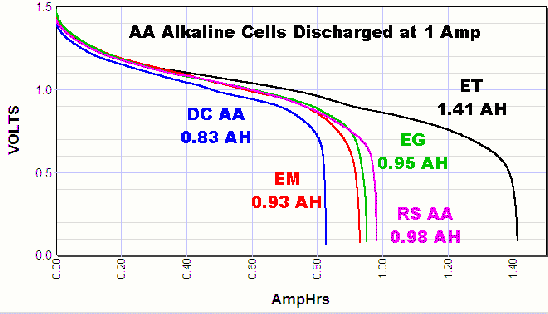
Under such a load, the supplied voltage drops a great deal very soon in these batteries (especially that I did not buy the most expensive ones), and you enjoy the low voltage problem again.
3. problem: inrush current
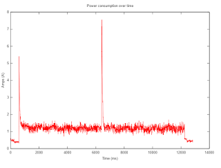 Inrush current in my robot car (starting and reversing the motors)
When a motor is turned on (or when the robot hits an obstruction and stalls the motor) the motor pulls much higher currents than it does in normal operation. This high current may pull down the battery power rail enough to reset all the digital electronics in the system (the electrical noise generated by DC brush motors may also cause the electronics resetting).
There are some common solutions for this problem:
- use two power rails + batteries; one for the motors and for the electronics and communicate by the means of optocouplers
- add capacitors directly across the battery; large electrolytic capacitors can eliminate the current spikes, small ceramic ones can reduce the RF noise [1,2]
- use an integrated load switch
4. problem: power distribution
There is one more final problem. As it can be seen on the wiring diagram above, the batteries are connected to the motor driver, and the voltage regulator of the motor driver powers the microcontroller. This is very unlucky. Copying from here:
The common section of wire will act as the small resistor and when the motor turns on and draws a large surge current, the electronics will see a large current drop.
The solution is simple, just connect everything directly to the battery (called star power distribution) if possible. In my case, there was nothing to avoid me connecting the Arduino directly to the battery as it has its own voltage regulator.
Conclusion
Most of these problems can be solved using a battery that supplies enough voltage and current that inrush current goes unnoticed. This can vary from system to system, in my case a 3 cells LiPo battery (11.1V) solved the problem. LiPo batteries are great for robotics purpose. They come in many different capacities and voltages (LiPo cells have a nominal voltage of 3.7V, a battery usually contains 1-5 cells, that is 3.7V-18.5V), and have phenomenal peak discharge rate (even up to 100x of their nominal capacity, but 20x-30x discharge rate is very common).
However, a powerful battery does not solve all of yours problem. Even if inrush current does not make your robot resetting by the voltage drop, it still can damage connectors and terminals and generates noise on the power rail that might confuse or even destroy delicate electronics. Some filtering capacitors (or an integrated load switch) are really helpful to limit the peak current and reduce electromagnetic noise.
What mistakes did you make as a beginner?