One of my ongoing projects is a very low-power electronics device that supposedly runs on a single-cell Li-Ion or Li-Polymer battery for a very long time, hopefully many-many months. In my idea, the battery actually could be a rechargeable one, e.g. LIR2032 or LIR2450 button cell, and I might also be able to recharge them during these months from a small solar panel, so ideally it runs “forever” with a single battery.
I looked for charger circuits and found out there are many incredibly cheap single-chip solutions available. For some reason I do not remember any more, I picked the MCP73831 chip, which is a very small, single-cell Li-Ion, Li-Polymer battery charger IC.
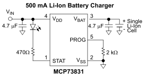
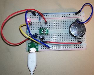
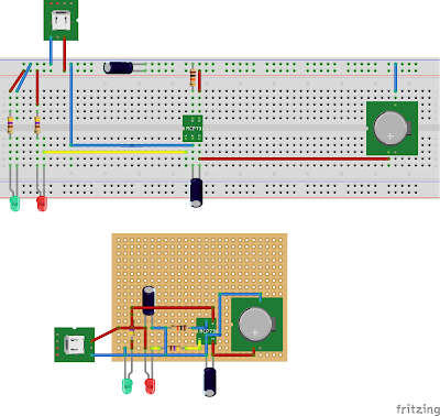
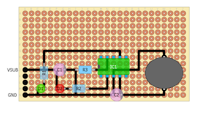
To be able to experiment with the chip, I just took the typical application schematics from the specification and created breadboard and perfboard diagrams. In this post I just want to share these diagrams as they maybe useful for others as well.
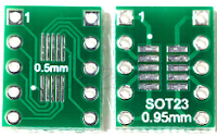
This chip is coming in a SOT23-5 package, so it is actually too small for prototyping; first of all, it must be converted to DIP format using a SOT23 to DIP adapter board. I used a DIP10 one, because that was at home, but there are other, smaller variants (less legs) as well.
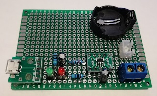
The diagrams are slightly modified. First of all, I replaced the 2K resistor with a 10K one, so it has 100mA output instead of 500mA. I also added one more LED indicating incoming power. So, the green LED is always on, the red LED indicates the charging status.
- Blinking: no battery / battery fault
- On: battery is being charged
- Off: battery is fully charged
I created Fritzing diagrams, and also a DIY Layour Creator one for the perfboard diagram as I find it nicer than the Fritzing one:
And finally, the realization. Two remarks: 1. I added some more connectors to the perfboard to make it more useful 2. A single-sided perfboard would be sufficient, and would look nicer, but I had only the double-sided at home
