Pulse Width Modulation (PWM) can be an extremely confusing subject for a beginner. Mainly, because it is often explained as a way to provide analog output by microcontrollers (there are also many excellent sources though). This tutorial at Arduino says in the second paragraph that
Pulse Width Modulation, or PWM, is a technique for getting analog results with digital means.
Which is very confusing at the least, especially that it follows:
Digital control is used to create a square wave, a signal switched between on and off.
It turns out that the PWM signals for various analog values are these:
This used to confuse me for a very long time. By analog signal, I rather imagine something like this:
What is PWM for then? It can be used when some kind of physical mechanism is involved that averages out the PWM signal. The brightness of a LED can be controlled for example (humans cannot perceive high frequency changes). With some effort, it can be done with a nice result (I mean without apparent flickering). It also can be used to control the speed of a DC motor, where the mechanical inertia of the rotor acts as an averaging mechanism. Probably there are other direct usages as well.
Still, the question remains, how to produce “real” analog output?
The answer is that one still needs to apply a small piece of electronics, a digital to analog converter (D/A), to the PWM signal. In this case, the simplest version of a passive analog low pass filter can do the job:
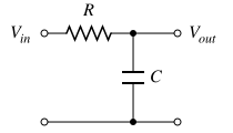
It is well explained in details in this article.
Intuition says that this works as one expects the capacitor in parallel to smooth the signal. Still, it is a general “low-pass filter”, how come it applies to this task? It may be immediately clear for an electric engineer, but I had a hard time understanding it until I found this article. It uses a completely different approach for the explanation, based on the Fourier analysis of PWM signals. If you understand the language of Fourier analysis, I recommend reading it, the theory is simple and beautiful (and quite obvious to be honest, seemingly it was too long ago when I studied this). In a nutshell, filtering is used to get the DC coefficient (what is the mean value) by removing all the higher harmonics.
Certainly there are many reasons behind that PWMs are widely adopted in almost all microcontrollers. One of these may be efficiency and its direct consequence, straightforward heat management. The transistors involved in generating PWM signals are either fully on or fully off (power loss is very low), thus do not dissipate much heat (no need for huge heat sinks). Another common argument in favor of PWM is that it always provides full voltage for a variable amount of time, thus, e.g. in the case of a motor drive, it can efficiently provide full torque from zero speed to full speed.
Did you have any basic concept hard to grab first as a beginner?