Overview
In this post I explain a capacitive proximity / touch sensor for Arduino based on a square wave generator rather than charge time measurement as the popular CapSense library. This design results in very stable sensor readings and it also works from a battery. It is compatible with virtually every Arduino board and even with most ATtiny chips.
How it works
It uses the very same technique as the beautiful musical instrument, the theremin, only it operates on a much lower frequency (around ~60KHz instead of some MHz) and uses square-wave signals for the sake of easier counting. So let me paraphrase a simple explanation of its working principle from theremin.info:
By using an alternating current of suitable frequency, tones of varying pitch are easily obtainable. A small vertical rod is used as the antenna. When the instrument is in operation, electro-magnetic waves of very weak energy are generated around this rod. These waves are of a definite length and frequency. The approach of a hand, which is an electrical conductor, alters the conditions in the electro-magnetic field surrounding the antenna, changes its capacity and thus affects the frequency of the alternating current generated by the apparatus. In this manner, a kind of invisible touch is produced in the space surrounding the antenna, and, as in a cello, a finger pressing on a string produces a higher pitch as it approaches the bridge, in this case also, the pitch increases as the finger is brought nearer the antenna.
In summary, stable, ~60KHz square-waves are generated by an RC oscillator. The capacity of an approaching hand causes a slight drop in this frequency what is detected by an Arduino based frequency counting library.
The square-wave generator
The sensor uses a Schmitt trigger based square-wave generator; this was the simplest suitable circuit I could find for this purpose, it consists only of three very cheap, commonly available parts: a capacitor, a resistor and a 7414 Schmitt trigger chip. The frequency of the output signal can be calculated by the following formula:
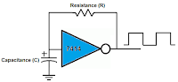
freq = 1.2 / (R*C)
With some experiments, I found that 60Khz base frequency fits nicely my initial goal of starting to sense around ~15cm. I achieved this by choosing C = 100pF and R = 200KΩ.
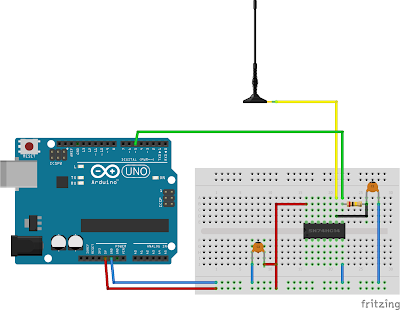
In summary, the part list and a lovely Fritzing diagram for the whole sensor:
- C1 = 100 pF
- R = 200 KΩ
- IC = 74HC14 Hex inverting Schmitt trigger
- C2 = 100nF (optional, but recommended)
The software
In a perfect world, all one should do is to constantly measure the frequency of the oscillator and compare it to the expected (60KHz) frequency. At proximity, the frequency drop is small (some hundreds Hz) and more or less linear with the distance. At touch, there is a huge, sudden, non-linear frequency drop. With some experimentation one can easily determine these frequencies to get an idea how to interpret an actual frequency measurement.
However, we do not live in a perfect world:
- The actual value of a resistor or capacitor is precise only to the extent of some tolerance (so you never get 60Khz, only if you buy high precision parts)
- The actual value of a capacitor is dependent on the current temperature, voltage, … (e.g. the frequency is drifting with time)
- The actual frequency is influenced by environmental noise (just put the antenna closer to your laptop to verify this)
To get proper, stable result, these problems must be handled. Probably there is no one, ultimate solution for these issues, rather, the solution vary from application to application. For my purposes, I found the following heuristic satisfying:
Instead of using the measured frequency directly, two lines of frequency measurements are maintained through an exponential filter. A baseline, with a huge weight (0.995), and current line with a smaller weight (0.75). Their values are initialized in the setup().
float current_line;
float baseline;

void setup()
{
  // https://github.com/domoszlai/arduino-frequency-counter
  current_line = baseline = count_frequency();
}

void loop()
{
  unsigned long f = count_frequency();

  current_line = current_line * CL_WEIGHT + (1 - CL_WEIGHT) * f;
  baseline = baseline * BL_WEIGHT + (1 - BL_WEIGHT) * f;

  ...
}
The baseline contains the base frequency, the frequency expected when proximity is not sensed. However, the baseline is not static: because of the exponential filter, it very slowly follows the changes of the current frequency measurement. This way, drifting of the base frequency is handled. It has, however, the side effect, that the system slowly adapts to proximity…
The current line also follows the changes of the current frequency measurement, but, because of the smaller weight, in a much faster pace. In this case, the exponential filter is applied only to smooth the frequency measurement.
A relative distance of the proximity can be computed easily now by proportionate the difference of the baseline and the current line to the maximal expected frequency drop:
// distance is reciprocal, bigger value indicates smaller distance
// and its range is 0-255
int diff = max(0, base_line - current_line);
if(diff < MAX_EXPECTED_FREQ_NOISE) diff = 0;
int distance = diff * 255L / MAX_FREQUENCY_DROP;
distance = min(distance, 255);
Finally, putting everything together:
// https://github.com/domoszlai/arduino-frequency-counter
#include "frequency_counter_TC.h"

//#define DEBUG

#define MAX_FREQUENCY_DROP        500
#define MAX_EXPECTED_FREQ_NOISE   30
#define CL_WEIGHT                 0.75
#define BL_WEIGHT                 0.995

float current_line = 0;
float baseline = 0;

void setup()
{
#ifdef DEBUG
  Serial.begin(9600);
#endif

  current_line = baseline = count_frequency();
}

void loop()
{
  unsigned long f = count_frequency();

  current_line = current_line * CL_WEIGHT + (1 - CL_WEIGHT) * f;
  baseline = baseline * BL_WEIGHT + (1 - BL_WEIGHT) * f;

  // distance is reciprocal, bigger value indicates smaller distance
  // and its range is 0-255
  int diff = max(0, baseline - current_line);
  if(diff < MAX_EXPECTED_FREQ_NOISE) diff = 0;
  int distance = diff * 255L / MAX_FREQUENCY_DROP;
  distance = min(distance, 255);

#ifdef DEBUG
  Serial.print(distance);
  Serial.print(" ");
  Serial.print(f);
  Serial.print(" ");
  Serial.print(baseline);
  Serial.print(" ");
  Serial.println(current_line);
#endif
}
Implementation notes
- The oscillator is prone to the instability of the input voltage. A standard USB 5V can be quite noisy; in my case, switching to regulated 3.3V reduced the frequency deviation by 50% the least. A voltage regulator is especially important, if it runs on a battery where voltage may drop as the load increases
- Avoid breadboards. The parasitic capacitance of an average breadboard messes up the frequency spectrum so much, it is hard see the peaks
- If ATtiny is used as frequency counter, it is essential to use an at least 8MHz external crystal. For a frequency counter, a stable timebase is essential; for this purpose, the internal oscillator of an ATtiny is just not good enough (this video is gold on the stability of oscillators)
- If you want to increase sensitivity, try increase the base frequency (and the size of the antenna). In this case, you might want to try an LC oscillator instead of the RC one, as they tend to be more stable
- It also make sense to decrease sensitivity, especially for a touch sensor. In this case 15-20Khz base frequency must be enough
For what would you like to use a proximity sensor?